Pages

Saturday, March 12, 2016

Bandit 1200 Carburetor Cleaning Part 1 - Carburetor Removal

Bandit's warm-up problems continued to get worse. Crappy idle, bad mileage, cylinders cutting out. No amount of SeaFoam or StarTron seemed to help so I decided to pull the carbs and clean 'em out.

Required supplies are a can of Maxima contact cleaner and a can of Berryman's B12 Chemtool.

Allow a couple of hours to remove the carburetors from the bike.

Easy stuff: remove seat, tank, side panels. Remove the tank bracket behind the air box.


Remove air box bolts.


Adjust throttle cables for maximum slack at the right grip, the remove 3 screws from throttle housing and disconnect throttle cables at the grip.


Pull throttle position sensor connector at the right side of the carburetor.


Disconnect choke cable at the carburetor end.


Loosen air box clamps.


 Loosen clamps at the intake boots.


There is an overflow hose on each side of the carburetor that needs to be unclamped.


Remove vacuum hose from carburetor 4.


Loosen throttle cables at the carburetor end. Pull the air box back toward the rear of the bike, disengage it from the carburetor air intakes. Pull the carburetors toward the back of the bike, and down, to release them from the intake boots. This requires some force.


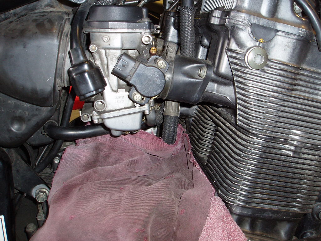
Put a rag over the engine to protect the paint, then pull the carbs out on the right side of the bike.


Be careful of the overflow hoses.


With the carbs halfway out, remove the front (push) and rear (pull) throttle cables.


The rear throttle cable can be difficult. Removing the fuel hose can help free space to remove it.


Finally remove the carburetors the rest of the way.


My Bandit's carburetors are covered in black grime--old gas and dirt.


Note: it is highly recommended to wear eye protection before using any type of aerosol spray cleaner!

I zapped the exterior with contact cleaner, trying not to get any in the round ports on either side. After using up an entire can it was cleaned up pretty well.


 Stay tuned for part II, cleaning jets and float bowls.

Tuesday, February 9, 2016

Bandit 1200 Carburetor Sync

After a few weeks of riding through heavy rain the Bandit started idling on 3 cylinders and stalling at stoplights. On acceleration it would fire on all 4 so I suspected either the carb sync I did a few weeks ago was way off, or some dirt got into one of the carbs somehow and plugged the idle circuit. I haven't changed the plugs in 37k miles so that could be an issue as well.

The first thing I did was dump a half can of Seafoam into the tank and top it off with Chevron 91, then ran it about 10 miles. This seemed to smooth it out at speed but the issue soon came back.

The canonical fix for this is to pull the carbs, take them apart, clean everything out with B-12, and reassemble. That is a lot of work. Ultimately that's probably what I'll end up doing, but it means a lost weekend so one looks at easy things first. The easiest thing I could think of was to re-do the carb sync and run a high concentration of fuel system cleaner through it.

Carb sync is not a difficult service but there are some potentially frustrating parts. Allow about 3 hours for the first time.

Specialty tools required: vacuum gauge ("Manometer"). I use a Morgan Carbtune which uses steel instead of mercury vacuum gauges. Also a maintenance gas tank, or long length of fuel hose, to connect the gas tank to the fuel line while adjusting carburetor vacuum. I bought a half gallon Craftsman lawn mower tank on eBay for a couple bucks for this service.

The first step is to remove the gas tank. That is fairly straightforward and I believe I've documented it elsewhere. Important things to note, remove the petcock lever first, and put a rag under the fuel line to catch fuel that comes out of it or the petcock.


Next, cover the alternator with rags to prevent anything from getting into it. Then, using a bent long-jaw needle nose pliers, or similar, remove the tiny rubber caps from the fittings on carbs 1 - 3. They have little wire clamps. I've found it's easiest to just pull the cap and make sure the wire clamp stays attached. They are hard to see and even harder to get at. It's easiest to remove them by pulling them up at an angle toward the right side of the bike.


There is one directly under the choke cable. It can help to unhook the choke cable and/or front throttle cable to get room to remove the cap. The wire clamps are magnetic if one falls into a hard-to-reach place.

The vacuum fitting on carb 4 has a hose instead of a rubber cap. Remove the hose, tape up or otherwise block both ends to prevent vacuum leak. Then hook the Carbtune vacuum hoses to fittings 1 - 4 in order.


Attach maintenance tank to the fuel line and fill with gas. Due to the firing problem I added a half can of Seafoam additive to the half gallon of tune-up gas. Very high concentration of additive.


Before starting the bike it's a good idea to have some fans pointed at the oil cooler. As Bandits are air cooled they will overheat if run for too long without air flow.


Start the bike and watch the Carbtune indicators. Due to the high concentration of additive there was a lot of popping from the exhaust. At 1750 RPM all carbs should be at the same vacuum reading as #4 (far right).


This can be extremely difficult to get exactly right. The adjustment screws are difficult to see, and as the adjustment for one carburetor changes, the rest can also change.

If any carburetors are out of sync turn the adjustment screw to equalize them. In my experience clockwise reduces the vacuum reading (lowers the indicator) whereas counterclockwise raises the indicator. Except sometimes when the opposite seems to happen. In the end the photo above is about as close as I could get them. Carburetor #4 is the index which the rest should sync to.

In practice syncing to 1750 RPM is a guideline at best. The carburetors should be in sync at a variety of RPMs from idle to 2k+. It's a good idea to check them at a range of RPMs and find where they're in sync at the widest RPM range.

After the sync is complete shut off the bike and replace the vacuum caps, pushing them down at an angle from the right side of the bike. Then reattach the tank.

I waited 10 minutes for the fuel additive to settle, then started the bike again.  Due to the high concentration of additive there was a lot of smoke from the exhaust after the bike was restarted. I let it idle for 5 minutes or so, then shut it off and re-attached the tank.

After a few days of running a lower concentration of additive in the tank all cylinders are firing. So with some luck I might not need to pull the carbs and clean them out. Will know in a few days.


Saturday, January 9, 2016

Bandit 1200 Valve Clearance Inspection - Addendum

After a week of commuting I noticed a couple of things. First, while the carb sync smoothed out the idle, it also reduced the idle speed about 100RPM which caused stalls during warmup. Not a big deal although getting the idle speed just right on the old air-cooled Bandit is fiddly.

Second, and more seriously, I noticed some oil seeping from the oil banjo bolts on the valve cover.


Not a lot of oil as the level in the sight glass was still Ok. Still, something that needed to be taken care of and monitored. I cleaned off the oil and torqued down the bolts another 6 inch-pounds, to 83 in-lbs from 77 (about a quarter turn for each bolt, still well under official torque spec of 12 ft-lbs). They were noticeably a bit loose.


I'll ride it for another week and see if there is still any oil leaking.


Sunday, January 3, 2016

Bandit 1200 Valve Clearance Inspection Part 2

Reassembly

Obviously the next step is to bolt the valve cover back on. There are a ton of gaskets that need to be replaced, unfortunately they aren't cheap.


Clymer manual is a bit vague on how to seal the valve cover gasket in. It says to use sealer but does not say where or how much. My rule of thumb with sealer is to use as little as possible to get the job done. So here are the points on the valve cover where I applied a very small dab of sealer:


Next step is to press fit the valve cover gasket. The gasket can go in two ways and it's difficult to tell which is correct. Neither the Clymer manual nor the service manual are any help in this regard. Fortunately the valve cover is not completely symmetrical. On careful inspection there is a small angular bend at the front, and the gasket also has this bend. The gasket has a rubber tab which is confusing, it does not cover the metal tab on the valve cover.


In my case I also used some Ultra Black RTV sealer to plug the hole that the reputable shop in SF made when they tried to pry it off.

Next, slide the valve cover back in, while carefully not snagging any of the round gaskets on the cam chain. This took me a couple of tries. It is very important that the round gaskets stay in place.


Per instructions in the manual, put a dab of sealer on the underside of each of the semicircle tabs on the valve cover gasket. I do not believe this is strictly necessary but I always do it.


Next is the slow and painstaking process of bolting down the valve cover. Replace the banjo bolt washers and disc-shaped gaskets, clean all the bolts thoroughly with solvent and dry them.


Install the banjo bolts and finger tighten.


Next install the shoulder (gasketless) bolts and valve cover bolts finger tight. Then tighten all bolts a quarter turn in criss-cross pattern in the following order:

  1. Inner banjo bolts
  2. Outer banjo bolts
  3. Shoulder bolts
  4. Inner valve cover bolts
  5. Outer valve cover bolts

Repeat the quarter-turn tightening sequence by hand, over and over, until all bolts feel just a little bit snug. It may take 6 - 8 iterations.

After all bolts are slightly snug (slight resistance to turning) it is time to break out a good-quality inch-pounds torque wrench. Set to 40 in-lbs and repeat the quarter-turn tightening sequence until all bolts are at 40. Then set it to 60 and repeat. Finally set it to 77 in-lbs and tighten all bolts in sequence until they are at 77. Some bolts will need to be hand-tightened as there is not enough clearance for a torque wrench. Make sure they feel like they are similarly tightened, or slightly less tight, as the bolts measured by the torque wrench.


Note that the manual will state 10 ft-lbs for valve cover bolts and 12 for the banjo bolts. IMO that is excessive. The goal here is to maintain oil pressure and prevent leaks, and 77 in-lbs is enough. [Edit: after a week the banjo bolts were leaking a tiny bit, so I tightened them to 83 in-lbs--see addendum.] The added torque will simply make the valve cover more difficult to remove next time and put undue stress on delicate threads in the cam caps and cylinder head. 77 in-lbs is plenty.

Next put a new o-ring in each of the oil hoses and torque them down. The manual calls for 88 in-lbs but again, 77 is plenty.


Next step is to reattach the breather. There is a tab on the gasket to orient it properly.


There is no torque spec associated with the breather. Slightly snug is all.


Reattach the PAIR valve and hoses. It's easier to put the hoses on the valve before bolting the valve onto the frame.


Finally it's a good idea to clean the air filter by blowing compressed air into the engine side, after valve service. Unscrew the 2 air box screws, remove the air filter, and blow compressed air into the back side of it. Replace at 32k miles or if it's filthy.


After the valve clearances are within spec it's a good idea to synchronize the carburetors. I will detail this in a separate write-up, suffice to say it requires a carb-tune manometer tool, at least one fan, and a lawn mower gas tank. Carbs 1 -3  should be adjusted to match carburetor #4 at 1750 RPM. In practice this is nearly impossible so good enough is good enough.


Friday, January 1, 2016

Bandit 1200 Valve Clearance Inspection Part 1

No rest for the wicked. Having just finished the FZ1's regulator/rectifier connector fix I noticed the Bandit, at 97k, was about 1k miles overdue for a valve clearance inspection.

This is not a difficult service after you've done it once although there are a lot of steps. The Bandit does not use shim valves so cam removal is not necessary for valve adjustment. In the old days I could do the entire tune-up including valve adjustment, carb sync, and air filter replacement in 4 hours. I'm slower and more careful now, the valve clearance inspection by itself is 5 - 6 hours for me now.

Gasket List

You'll need the following gaskets. Sometimes you can get away with re-using them but I find they're less likely to get stuck and leave residue if they're replaced every time.

  • Gasket, cylinder: 11173-06B03
  • Signal generator cover gasket: 11491-27A30
  • 4 x oil journal bolt washer (Gasket): 09168-08029
  • 8 x valve cover bolt gasket (Washer): 09161-11008
  • 2 x oil hose o-ring (O ring): 09280-14011
  • 2 x spark plug gasket type 1 (Gasket, head cover): 11178-27A02
  • 2 x spark plug gasket type 2 (Gasket, head cover): 11179-27A03


Note, photo also includes a cam chain tensioner gasket and APE cam chain tensioner which are not required for this service.

Seat and Tank Removal

1st step is to remove the seat and tank. For tank removal first unscrew the petcock lever, remove the bolts at the rear of the tank, then raise the tank, support with 2-by-4 at low height, remove rear vent hoses, and unplug the fuel gauge sending unit. Then move the 2-by-4 to the tall height, and remove the vacuum hose and fuel hose from the petcock. Put a rag under the fuel hose to catch any fuel that comes out.


Put the tank on a milk crate or box to avoid supporting the weight of the tank on the petcock. This can cause gas leaks down the road.

Seat and tank removed
Valve cover removal
  • remove the 4 hoses from the PAIR valve on the right-hand side of the frame, then remove PAIR valve from its frame mount with the single hex bolt.
  • Unplug spark plug wires and move them out of the way
  • Remove the breather hose from the breather on top center of the valve cover, then unbolt the breather and remove it and its gasket.
  • Unbolt the two oil hoses from the back of the valve cover and throw away the o-rings. These need to be replaced.
  • Unbolt and remove front and rear "shoulder bolts" from the valve cover (hex bolts with no gaskets underneath).
  • In a criss-cross pattern, in several steps, unbolt the black hex bolts that hold down the valve cover, and the 4 silver-colored oil journal bolts that run down the center of the valve cover.


Gently pry up the disc-shaped gaskets from the valve cover and throw them away. They will need to be replaced. Also throw away the metal washers underneath the silver oil journal bolts, those need to be replaced as well.


Finally remove the valve cover by lifting it straight off, and gently working it out on the left side. Most likely the valve cover will be stuck hard and it can be very difficult to remove. Whatever you do, resist the temptation to wedge a screwdriver in there and pry. That is a sure way to damage the surface of the valve cover and/or cylinder head, and possibly even put a chip or hole in the valve cover. I used to take my bike to a reputable shop in SF to have valve clearance inspection done, and as a result have a crescent-shaped hole in my valve cover, presumably from where a mechanic jammed a screwdriver in there to pry it loose. You can hit it with a rubber mallet, which sometimes works, or tie some twine around two hex bolts protruding from either side of the valve cover and lift up. That's how I got it unstuck this time.

With the valve cover off you can see the valves, cams, and cam chain.


Signal Generator Cover Removal

If you have engine guards, which you should, the right-side guard will have to be moved aside to remove the signal generator cover. It is not necessary to totally remove the engine guard. Remove the hex bolt and loosen the 17mm bolt at the top of the engine guard. The nut at the back of the 17mm bolt is very hard to see,it is 14mm. Hold it with a wrench while loosening the bolt. There is a 3rd bolt at the bottom of the guard which is missing from my bike. That has to be removed. Then swing the engine guard forward.


Next remove signal generator cover by removing all hex bolts. Note the bolt at the top has a washer. Had to whack the cover with a rubber mallet to get it loose.

Valve Clearance Inspection

With the cover off, rotate the motor clockwise with a 19mm wrench into the 1st valve adjustment position--cam markers facing outward and the "T" mark on the signal generator at the left side contact. In this position #1 and #3 intake, and #1 and #2 exhaust valves can be measured.


To measure valve clearance a feeler gauge is needed. Clearance:
  • Intake:    0.10 - 0.15mm / 0.004 - 0.006"
  • Exhaust: 0.18 - 0.23mm / 0.007 - 0.009"
To adjust the valves a Suzuki valve adjust tool and 8mm wrench are needed to loosen the valve lock nut and turn the adjuster.

My feeler gauge has blades for 0.004, 0.005, and 0.006 for measuring intake, and 0.007, 0.008, and 0.009 for measuring exhaust. My goal is to set the valves for the middle clearance.


To check the clearance, first insert the smallest of the 3 blades into the space between the rocker and valve stem. It should go in easily. Then insert the middle feeler gauge. Ideally it would go in with slight friction. Finally insert the widest, which would either not go in at all, or go in with moderate force. If any of the valves are not within spec, first loosen the lock nut with the 8mm wrench, turn the adjuster with the adjustment tool., then retighten the lock nut.


Next turn the motor to the 2nd position with cam markers facing inward and the signal generator rotor "T" mark on the signal generator at the left side contact. In this position #2 and #4 intake and #3 and #4 exhaust can be measured.

If any valves needed to be adjusted rotate the motor into position and check again.

Reassembly

Peel off the old signal generator cover gasket and replace it. If any gasket material is stuck to the cover or the engine facing it must be removed, ideally with something that won't scratch the surface, e.g coffee stirrer stick, plastic fork, wooden chopstick, or similar. If none of those work a razor blade can be used to trim off the old gasket, but must be done with extreme caution. A steel blade will scratch the aluminum engine surfaces.


Add a small amount of gasket sealer to 3 areas of the signal generator surface: the rubber strip at the top, and a small dab on the left and right sides where the crankcase is bolted together. I use Permatex high tack 97B.


Press-fit the gasket. It will only go on one way.


Bolt on the signal generator cover. It does not have to be tight at all. Finger tight + 1/8 turn is all. Remember the bolt with the washer goes on top.


Finally rotate the engine guard back into position. Bolt in the hex bolt, and tighten the 17mm bolt at the top of the engine guard. The nut behind is 14mm, hold it with a wrench. There is a 3rd bolt at the bottom which is missing from my bike.

Next, remove all the old gaskets and clean out all the sealer residue from the valve cover. Spray it down with contact cleaner, then use a wooden chopstick and rag soaked in solvent to get all the old sealer out of it. It should look pretty clean when done.


This was about 3 hours work for me, and all I had time for today. Next steps, sealing in the new valve cover gaskets and bolting the cover back onto the cylinder head.