Pages

Showing posts with label other routine maintenance. Show all posts

Tuesday, September 17, 2013

FZ1 Oil Change

This is a simple service but also easy to mess up.  There is an excellent write-up on Pat's Motorcycle Page.

Tools Required
  • 17mm socket
  • oil filter socket
  • oil funnel
  • drain pan
  • aluminum foil
  • nitrile gloves

Supplies
  • 3.1qt Yamalube 20-40 or equivalent*
  • oil filter:  Emgo 10-22222, 10-22232, 10-22230, or equivalent
  • crush washer, Yamaha part #214-11198-01
  • rags
  • cardboard

Procedure

This is easier to do with the bike on the center stand but it does not have to be.

Warm up engine for about 10 minutes.  Turn off, then loosen or remove oil filler cap.


Remove drain bolt on opposite side of motor with 17mm socket and allow oil to drain.


It is helpful to put the bike on its side stand to drain out the last bit of dirty oil from the oil pan.


Place aluminum foil on exhaust headers to prevent oil from contact with hot exhaust pipes.  Remove oil filter using oil filter socket.  Ensure oil filter gasket is attached to filter, not the motor.


Place a new crush washer on the drain plug, flat side toward motor.  Crush washer direction is important.


Bolt in the drain plug.  Manual says torque to 31 ft/lbs.  I just do finger tight + 1/8 - 1/4 turn.  This does not need to be tight, the crush washer will seal at low torque.  The risk of damaging threads is much greater and more difficult to repair than the risk of losing a little oil.  The plug will not fall out.

Put clean oil on the new filter gasket, then bolt on the filter.  Manual says 12 ft/lbs. but again finger tight + 1/4 turn is plenty.  Do not over tighten.


Chrome

Refill with 3.1 quarts of appropriate engine oil.  Do not overfill.  I mark the bottle so I know when to stop pouring.


After filling with the appropriate amount, run the engine for 5 minutes.  The manual says to let the engine cool for a few minutes and check the level with the bike on the center stand.  In practice I've found the oil level continues to rise in the glass for an hour or more and will read low if checked too soon.  Do not overfill, wait at least an hour before checking.

Oil at correct level
That's it!


* Note:  Yamaha no longer sells Yamalube 20-40.  From browsing the FZ1 list my understanding is they now recommend Yamalube 20-50 or equivalent non-synthetic oil, however many FZ1 owners switch their bikes to full synthetic.

Monday, September 9, 2013

FZ1 ExUP Service

September 8, 2013

Tools Required
  • 8mm socket and hex key
  • Center punch or other small metal rod
Supplies
  • Kerosene and tooth brush
  • Contact cleaner 
  • WD-40 
  • Tri-Flow cable lube 
Pat's Motorcycle Page has an excellent and thorough write-up about Yamaha exhaust valve maintenance.  I don't have a lot to add to it, besides that the copper anti-seize I used for this service 12k miles ago was completely gone without a trace.  The valve wasn't seized but I expected the anti-seize to last longer than that.

The other thing is that the orientation of the valve is a bit counter intuitive.  During exhaust valve operation the curved valve faces toward the front of the bike, and rotates clockwise upwards as RPMs increase.  I would've thought it faced the rear of the bike and rotated the other way, but there are only so many ways it can go back in and that isn't one of them.

I started by putting WD-40 on all the bolts holding the valve in.  They are subject to heat and corrosion, and it would be a pain to snap one and get it stuck in there.

ExUP removed, seen from front.  Front of bike at left
To clean it I brushed everything with kerosene, then washed with contact cleaner and reassembled after the solvents had dried.

ExUP, top view.  Front of bike would be at right
ExUP rear view, front of bike at right


For completeness remove and clean the pulley, and use a clamp-on cable lube tool to shoot Tri-Flow into the cable housings. Spray contact cleaner into the header port where the far side of the valve seats, then dry with compressed air.

ExUP removed.  Valve is on left at reassembly
Post-cleaning Alignment

After reassembling and adjusting the cables, to ensure the ExUP is operating correctly run the bike with the ExUP cover off and observe whether the pulley can rotate freely.  If so, turn off the bike, then turn the key back to the ON position.  The servo motor should bring the pulley so that the alignment rods are centered over the alignment hole on the left side of the mounting bracket.  If the rods are not centered correctly adjust the cables (right side of bike under tank) and repeat the procedure.  Note that the cable housings are color-coded silver and black for easy identification.

Notes for Easier Reassembly

There are a few small parts that have to go together in the correct order. To reattach pulley: silver ExUp cable goes on top (over top of pulley), black cable goes on bottom (underside of pulley). Order of pulley parts: 1.) ExUp face plate, 2.) large washer, 2.) pulley spring with large side toward large washer, 3.) pulley, 4.) pulley washer, then bolt. Bolt pulley securely by putting a rod or hole punch between the U-shaped bracket that faces towards the front of the bike, into the alignment hole on the valve face plate. Then bolt can be tightened without moving the pulley.

Cable adjustment notes: to loosen cable turn adjuster towards front of bike - less adjuster threads showing. Tighten is opposite - more threads showing, adjuster moves toward rear of bike.

Sunday, April 22, 2012

Bandit Oil Change

April 8, 2012

An oil change is a quick service that's done frequently so it might not seem worth documenting.  But, I've read enough BARF posts by newer riders who aren't sure how to check their oil, much less change it, that I think it's worth a short writeup.  Plus, if done incorrectly it's possible to do major engine damage by over-filling, under-filling, or stripping threads.  My Bandit has a heli-coil in its oil pan, so I know from first-hand experience that it's possible to immobilize a bike by performing this service incorrectly.

Time required is 30 minutes to an hour.

Required supplies:
  • 21mm socket
  • Oil filter socket
  • Drain pan
  • Oil
  • Filter - Emgo 10-55660 or equivalent for the Bandit
  • Crush washer
  • Nitrile gloves
  • Cardboard
  • Foil
  • Trucker hat


I use Motul 3000 10w-40 non-synthetic in the Bandit, and a Cat Diesel Power hat.   I've tried many combinations of oil and hats.  Motul 3000 and Cat seem to work the best.


Warm up the bike for about 10 minutes and put it on the center stand.  Place cardboard under the bike, and put the drain pan under the drain plug.  Loosen the oil filler cap on the right side of the bike.


Set the ratchet to loosen by flipping the switch to the right.


Remove the drain plug.  Loosen by turning the ratchet toward the front of the bike.  The drain plug is upside down on the Bandit so it can be momentarily confusing figuring out which way to turn it.  Trust me, you do not want to turn it the wrong direction.


Let the oil drain.  It will never stop dripping so don't wait, 10 - 20 minutes is enough time.  Then put a new crush washer on the drain plug. Note, crush washers are directional. The larger flat side should go toward the drain pan, small side facing the plug.  The bike may leak oil if the crush washer is upside down.


Put the drain plug back in.  The torque spec is 17 ft. lbs.  You can use the spec if you want to, but having stripped the threads in my oil drain I believe 17 ft. lbs. is too tight.  Finger-tight plus a quarter-turn is enough.

Next, place the foil underneath the oil filter on the exhaust headers and remove the oil filter with the filter socket. A fair amount of oil may come out.


Make sure the filter gasket comes off with the old filter.


Apply clean oil to the new filter gasket, then fill the new filter about half full with clean oil. I don't remember what the oil filter torque spec is on the Bandit, but finger tight plus a half turn is plenty.


Next, fill the bike with new oil.  The Bandit takes 3.7 quarts, almost a full gallon.  Do not overfill.


Run the bike for about 5 minutes and check for leaks.  Then shut it off and wait for a few minutes.  The oil level should be just below the full line in the sight glass.


If the level is too low, fill gradually until the oil level is just below the full line.  If it is too full you will have to drain some oil out.  There isn't a clean way to do this that I know of.  The method I've used in the past is to get a second clean drain pan and drain all the oil out, then put most of it back in.  It's hard to drain just a little without the drain plug falling out.  Recycle the used oil and filter at a recycling center or used oil pick-up location.


Sunday, April 8, 2012

FZ1 Valve Adjustment Part V: Post-maintenance troubleshooting and Wrap-up

March 12, ongoing

After finally finishing the tune-up it rained all week. I don't take the FZ1 out in the rain if I can help it so I didn't have a chance to do a test ride until the following week. When I finally rode it to work I smelled coolant as I pulled into the lot. Looking closely I noticed coolant leaking from the water pump hose where it attaches to the radiator. So I tightened the hose clamp.

Upon returning home I propped up the tank, revved the engine, and looked for more leaks, but didn't see any.

Next day I rode to work and smelled more coolant but couldn't find any leaks. On returning home I waited for the engine to cool, then checked the coolant level in both the radiator and the overflow tank. Both were fine.

The following day I rode to work and smelled more coolant. After parking in the lot I put the bike up on the center stand and looked at the engine carefully with a flashlight. There was a pool of coolant on the right side of the valve cover in the indentation underneath the right side valve cover coolant hose. So I tightened that hose clamp, checked for leaks when I got home that night, and found none.


The following day it rained and I rode the Bandit to work.

The following day I rode the FZ1 to work and smelled coolant again. Once again I propped the bike up on the center stand and checked for leaks. I saw a drop coming out of the top end of the same right side valve cover coolant hose. I didn't have the 6mm socket and extension I needed to tighten it at work so I got to it at home. Also topped off the radiator and overflow tank.

It's rained most days since then so I haven't taken the FZ1 out since tightening the third hose clamp. I'm now carrying a 6mm socket and extension with me in my tank bag just in case. All of the leaks have been slow and hard to find, and the bike hasn't used much coolant.

Coolant leaks appear to have been the only mechanical fallout from this project so I'm grateful for that. The more important and lasting fallout has been the realization that this project consumed three entire weekends, a vacation day, and some weeknights in between, and I really don't have that kind of time to devote to routine motorcycle maintenance. In fact I really don't have much free time at all. During the valve service the dog didn't get walked, the house didn't get cleaned, I did no yard work, I didn't go to the gym, and all the other routine things I usually take care of were left undone, including taking care of the other bikes and the truck. I realized there are a nearly infinite number of opportunities to make major mistakes and cause serious engine damage during a procedure like this. I realized that, regardless of my relative level of mechanical skill, I work slowly. And I realized installing spark plugs makes me break out into a cold sweat. I'm not sure what the long-term implications are, or whether I'll attempt this service again. What I am sure of is that in another 26k miles I'll have at least four exhaust valves that need shims, and someone will have to do this again.

Tuesday, April 3, 2012

FZ1 Valve Adjustment Part IV: Reassembly

March 10 - 11, 2012

Having decided to do no further work on valve clearances it was time to put everything back together and see if the bike would run. Compared to bolting in cams and resetting the engine timing, reassembling the rest of the bike was not that hard, with a few exceptions.

I decided to change the valve cover gasket because it had never been done. The new gasket was floppy and wouldn't hold its shape, so it kept falling out of the valve cover when I flipped it over to put it back on the engine. The Clymer manual specifies not to use any sealer on this gasket, except for a dab on each one of the four semi-circular tabs. So I was momentarily stuck as to how I was going to get the gasket to stay in place. Eventually the problem was solved with a lot of masking tape. After that I very carefully bolted the cover down in a crisscross pattern starting from the inside. The torque wrench wouldn't fit in some of the spaces so I did the best I could with the bolts that couldn't be torqued to spec.

I then bolted the signal generator cover back on using a new gasket and no sealer, noting the locations of the two long bolts and locating dowel. The locating dowel goes through a hole in the plastic cam chain guide which aligns with a hole in the engine. None of it was lined up quite right and there was some messing around to get the dowel in correctly. The disassembly procedure calls for removing the cam chain guide which I thought wouldn't be necessary, but might have been a good idea.

Next issue was reinstalling spark plugs. I purchased four new iridium plugs (NGK CR9EIX), checked the gap (0.7mm - 0.8mm), put a small amount of anti-seize on the threads and dielectric grease on the tips. Due to some bad experiences stripping threads on the Bandit I'm extremely paranoid about stripping threads and cross-threading, especially on the cylinder head. So it took several hours and lots of turning, backing out, turning again, backing out, etc. until I was able to convince myself I wasn't cross-threading the spark plug holes, which I was never really sure of. Since the plugs are installed using the plug socket they can't be turned directly with fingers, so it can be hard to feel if they're going in correctly and it's impossible to see the plug threads. Cross threading the plug threads would mean pulling the head, and after three weeks of adjusting valves that thought was demoralizing. The Yamaha service manual specifies the plugs should be tightened to 9.4 foot-pounds. Being paranoid, I went with finger-tight plus a half turn, still wondering if I'd cross-threaded the plugs.

Eventually all four went in, cross-threaded or not, so I set about reinstalling the AIS. First I installed the blocky AIS valve and wasn't able to get the tubing in. So I took out the valve and installed the tubing, then I couldn't get the valve back in. After another few hours of messing with it I looked up Pat's AIS removal procedure and found Pat had removed the valve from the top of the engine, not side or front. So I removed the ignition coil for cylinders 2 & 3, installed the tubing, then the AIS valve last. The right side valve cover coolant hose had to be removed to get the AIS system back in.


AIS valve reinstall

When the AIS was finally back in it was time to reinstall the radiator and attach the plug wires. Neither presented immediate difficulties.

Before reinstalling the tank I removed the air filter and blew it out with compressed air, as per procedure in the Clymer manual. The airbox cover screws are a little hard to get to but not difficult when compared to the AIS. Also both of the black triangular side covers have to come off to remove the rubber airbox cover. The side covers are pressure-fit into the airbox cover on the top, and there is a plastic post that fits into a hole in the frame on the bottom.

The tank has two identical-looking breather hoses that attach to it toward the back. I marked one of them with a white dot to note that it was the hose on top, but now couldn't remember what I'd meant by "top" or which way the hose was oriented when I marked it. It would've been better to have put a white dot on the matching tank hose fitting as well. I didn't think of that. So I made my best guess, installed the hoses, and turned the fuel valve to ON.

With the tank and radiator reinstalled the next step was to fill the radiator with coolant and start the bike. The procedure for filling the radiator says to fill with 50/50 aluminum-friendly silicate-free coolant until it's full, fill the overflow tank to the low line, then start the engine and wait for the thermostat to open. After that the coolant should circulate throughout the engine and the level should drop, requiring topping off. So I did that, using a mixture of Prestone Extended Life coolant from the local auto parts store, and distilled water from the grocery store. That mixture is more cost-effective than buying pre-mixed coolant from the motorcycle shop, and can be used in the pickup also. Prestone Extended Life claims to be silicate free and safe for aluminum. In 26k miles I haven't had any issues with it.

I pulled the battery off the charger, installed it, and waited a moment to look for anything I'd forgotten to install or tighten. I found nothing lying around and everything looked like it was installed correctly. I wasn't certain that the engine wasn't 360 degrees off or what it would mean if it was, or even how to tell. I had rotated the engine a few times after remeasuring the valves the third time, and was pretty sure that at least there would be no valve/piston contact. This is always a possibility if the engine timing is off, and will basically destroy a motor in a split second. After a moment of silence and a deep breath I turned the key and hit the starter. It started immediately!

After the bike warmed up I topped off the radiator, capped it, and filled the overflow tank to the full line.

Nothing appeared to be leaking so I moved on to the last steps, carburetor synchronization and idle speed adjustment. On the FZ1 these are both relatively quick and easy with the right tools. Later I'll do a separate write-up about how to do a carb sync, but Pat's procedure is the definitive guide for the FZ1 and the procedure I followed.

Friday, March 30, 2012

FZ1 Valve Adjustment Part III: Setting Engine Timing and Valve Re-measurement

March 03 - 04, 2012

Thanks to the FZ1 list I had a path forward for reinstalling the cams. I tried to make progress during the week but that's always difficult due to my work schedule. However I was optimistic that I'd have the bike back together by the end of the weekend.

Even with help from the list installing cams is frustrating. There are guide holes in the cams that are supposed to line up with marks on the cam holders when the signal generator "T" mark is aligned with the guide mark on the frame (Cylinder 1 at TDC on compression stroke). However due to valve spring pressure the camshafts don't rest flat in the engine. At first I thought I must have bent them somehow. But they weren't bent, they just rest at an awkward position with some of the cam lobes touching the valve lifters, lifting the cam out of the journals. The cam position shifts as the cam holders are tightened down. So the camshafts may start perfectly aligned with the marks on the cam holders and shift as they're tightened into position. Also, between the two cams there are 6 cam holders and 28 bolts, all of which need to be tightened in order, starting from the inside working out, with great care, in multiple stages to 88 inch pounds. In other words, numerous possibilities for stripping threads, rounding bolts, and causing other damage to the cylinder head. I was eventually able to get the process down to about an hour per cam, tightening finger-tight first, then in stages to 55 inch pounds, then in stages to 88.


Cams bolted in with cam sprockets removed
Guide marks visible on right side (exhaust) cam if you look closely

Note: During this process it is important to keep track of the location of the cam chain. It will want to fall toward the front of the bike, in front of the intake cam, during cam installation. Once the intake cam is installed, if the chain is in front of it, it is not possible to reposition it toward the outside of the cam where it belongs. The intake cam then has to be removed and reinstalled, which in my case took another few hours after realizing this.


Intake cam guide marks
Can be seen behind coolant pipe

With the cams bolted in the sprockets can be bolted in underneath the cam chain. The exhaust sprocket goes first, wrapping the chain around it as tightly as possible. A single bolt goes in the sprocket, finger tight, to attach it to the cam. Then the intake cam sprocket, also bolted in with a single bolt finger-tight. If the bolt hole in the intake sprocket does not exactly line up with the hole in the cam while the sprocket is meshed with the cam chain, it means one or both of the cams are not aligned correctly and must be repositioned and reinstalled. I had to do this more than once, taking at least an extra hour her per cam. However this does make it more difficult to reassemble the engine with the timing wrong.

Assuming one gets past that hurdle the cam chain tensioner must be reinstalled before the engine can be turned to attach the second sprocket bolt on each cam. There is a procedure in both manuals for retracting the tensioner with a small flat head screwdriver so it can reinstalled in the engine.

Having done that, if the valves have already been re-checked the cam bolts should be backed out one at a time in order to apply a small bead of blue threadlocker, then torqued down to 17 ft. pounds. If, as in my case, the valves need to be re-checked, the bolts should be torqued to spec without threadlocker as the cams may need to be removed again.


Cams and sprockets reinstalled, finally
But not for long...

Having finally reinstalled the cams I checked the valve clearances again and discovered two exhaust valves that were tighter than I'd like, two more I'd adjusted that were still too tight, and two intake valves that were too tight. Looking at my supply of shims I realized I was out of 1.75mm and 1.80mm shims with only 30 minutes till the local dealer closed. So I set out for the shop by bicycle and cleaned out their supply of those two sizes. Upon returning I set about removing the cams again. Another day gone.

Sunday 03/04 I did the second round of shim math and swaps, reinstalled the cams twice after getting the engine timing slightly off the first time, and rechecked clearances again. I still had four exhaust valves that were tighter than I'd like, right on the edge of spec. So I was faced with either removing the cams again and shimming the four marginal valves the following weekend, or deciding the situation was improved to my satisfaction and to take no further chances stripping threads or dropping shims in the engine. I decided on the latter, wisely, I think.

Sunday, March 25, 2012

FZ1 Valve Adjustment Part II: Measurement and Adjustment

Feb 25 - 26, 2012

After disassembly the next step is to measure valve clearances. This was surprisingly easy just following the procedure in the Clymer manual, although there are 5 valves per cylinder for a total of 20. Why so many?

Unfortunately my tapered feeler gauges are at 0.03mm intervals so it wasn't always possible to tell exactly what the clearance was, but easy enough to tell if a valve was significantly off. With the cams at the proper position, insert the feeler gauge that is one below spec. Hopefully that slides in easily. Then slide in the gauge that is in the middle of spec. Hopefully that goes in with a slight amount of friction. Then insert then next larger gauge that is slightly thicker than spec. With my feeler gauge set the gauge larger than spec shouldn't go in at all. The clearance specs are:

Intake: 0.11 - 0.20
Exhaust: 0.21 - 0.25mm

Using this technique I determined that all the exhaust valves were too tight, and all the intake valves were tighter than I'd like, but technically within tolerance. Unfortunately this meant there would be no question about removing cams. But I knew that.

Following the Clymer manual procedure I removed the cams with the sprockets attached, after making white-out marks on the cam chain and sprockets so I'd be able to reassemble them without changing the engine timing. That made sense to me because that's how the Bandit and SV650 cams are removed. The procedure calls for first removing the cam chain tensioner and gasket after removing its cap and winding it so it stops putting pressure on the cam chain. Then tying up the cam chain with wire so it doesn't fall into the engine. Next removing the cam holders by loosening the bolts in stages, in a criss-cross pattern starting from the outside. Finally removing the cams. Unfortunately removing cams with sprockets attached was a mistake as I found out later. In the meantime I was able to pull the buckets with a stick magnet and check the shim size.


Cams pulled with sprockets attached, cam caps, and a fly


Cams removed showing tops of the buckets


Pulling buckets with magnet

Note: The correct procedure for removing cams involves positioning the engine at TDC on the exhaust stroke ("H" mark aligned with mark on frame), removing cam sprocket bolts, then turning the engine back to TDC on the compression stroke ("T" mark aligned with mark on frame, cam lobes pointed away from each other), then removing the remaining cam bolts. Finally removing the tensioner and the cam holders.

The cam holders are marked, so if one is familiar with the markings they won't get mixed up even if they're not stored in the proper position. The buckets, however, belong to a specific valve and must stay with that valve. So it was important to carefully store all the parts in order. The buckets are not labeled and have no distinguishing features.


Exhaust valve buckets, in order, with their shims

Here are the valve clearances and the exhaust valve shim sizes I found underneath the buckets.


Valve clearances

Shim Math

After pulling shims it's necessary to determine what shim sizes are needed to set the valves back within specification. From the Clymer manual the formula is:

New_shim = (measured_clearance - spec) + old_shim_thickness


So, if I want to set an exhaust valve to the middle of spec, 0.23mm, my measured clearance is 0.15mm, and the old shim thickness was 1.85mm, the new shim would be:

(0.15 - 0.23) + 1.85


Resulting in a new shim measuring 1.77mm.

Unfortunately aftermarket shims come in increments of 0.05mm, so my available options would be 1.75 or 1.80. More math:

1.80 = (0.15 - x ) + 1.85
1.80 = 2.00 - x
1.80 + x = 2.00
0.20 = x

1.80 won't work because it would result in a clearance of 0.20, which is 0.01 tighter than spec. Better to go with 1.75, which should result in a clearance of 0.25.

One additional complication, it's important to measure the shims that come out of the bike to make sure they're actually the size they claim to be. If they're worn so that they're not the indicated size, of course the math has to be done according to the actual size, not the indicated size. There is a chart in the Yamaha service manual that helps with this.


Measuring shim with digital micrometer

The new shims should go in number side up and should be seated correctly. They are a tight fit and it's easy to seat them at the wrong angle. They should be flat relative to the rest of the valve, and not stick out of the shim seat much at all.

Cam Reinstall
After installing the new shims the cams need to be reinstalled and the valve clearances double checked. The cams and everything they come into contact with need to be lubed with molybdenum disulfide grease during reassembly. So I did that and was eventually able to get the cam sprockets back underneath the cam chain. However the other ends of the cams, the non-sprocket end on the left side of the bike, were sitting high up off the engine and didn't seem to want to sit on the buckets properly. I got the feeling I was applying too much pressure to the cams to get them seated properly and thought I must be doing something wrong. Not knowing what else to do I asked for help from the FZ1 list and waited. They were quick to respond, but I'd wasted a lot of time trying to get the cams in with the sprockets attached, and the day was pretty much done.

It turns out that the Yamaha service manual has a different procedure for cam removal and the folks on the FZ1 list assumed I followed the Yamaha procedure. Yamaha says to remove the cam sprockets while the cams are still installed in the engine, and reinstall the cams without the sprockets attached. So I had to figure out how to remove the sprockets with the cams out of the bike, in order to reinstall the cams. Eventually I was able to accomplish this using the cam chain to hold the sprockets, while I kept the engine from rotating with one hand and loosened the cam sprocket bolts with the other. It was really awkward and there was strong threadlocker on the sprocket bolts. I'm lucky I didn't round any bolts or break anything. In retrospect it probably would've been better to remove the bolts with an air wrench and 10mm impact socket, but I didn't have an impact socket of that size lying around. It would have been better to have taken a break and gone to the hardware store.

Saturday, March 24, 2012

FZ1 Valve Adjustment Part I: Disassembly

Feb 24, 2012

I was anticipating this day without much enthusiasm as my Yamaha approached its second valve adjustment interval at 52k. The local dealer quoted $540 in labor plus parts to do this service so I figured I'd end up doing it myself. The last time I checked valve clearances on the FZ1 it was out of commission for 3 weeks and I didn't even pull cams to replace shims. This time I knew I'd have to because the specs were on the tight side several years ago at 26k. Ultimately with the help of the FZ1 Owner's List I was successful in getting the valves in spec and getting the bike running again, but it was out of service for three full weekends and a vacation day. I learned a lot about the bike and was very humbled as far as any pretensions of mechanical aptitude.

As the mileage approached I bought the gasket set: valve cover, cam chain tensioner, and signal generator cover gaskets, also iridium spark plugs. I double checked my supply of 7.48mm shims, coolant, distilled water, and micrometer batteries. Having done all that I was out of excuses so I took a Friday off work and got started.

The first step after removing the battery is to drain the coolant and remove the radiator. The very first thing that has to be removed is the right side cowling panel to access the radiator cap. I dropped one of the three cowling mounting bolts and spent an hour looking for it. It had landed in a crevice in my hydraulic jack underneath the work bench. Off to a great start.

The tank has to come off (2 bolts, 3 hoses, and an electrical plug) to access the radiator fan's electrical plug. I removed the right side plastic panel in order to access the coolant overflow tank and extract what coolant I could. This was all per Clymer manual.

Next I removed the radiator. This is only two bolts, three hoses, and the fan electrical plug. I had to lube the water pump hose with Tri-Flow in order to get it detached from the radiator, and got a big blob of Tri-Flow in the eye. After spending the next 10 minutes running water into my eye I remembered about safety goggles. Other than that, not too difficult.

Next, the Air Induction System. The AIS is a a spider-like mess of steel and rubber tubing running over the top of the cylinder head cover toward the front of the engine, terminating in a large cube-shaped valve toward the carburetor on one end, and 4 ports near the exhaust headers on the other:


FZ1 AIS System
Photo Courtesy FZ1 Owner's List

It is difficult to remove and even worse to reinstall. Many FZ1 owners remove it permanently using an aftermarket kit, and after this service I considered it. I'm all for clean air, but seriously. This is one of the most difficult parts of the procedure. Thankfully Pat's FZ1 Site has tips for removing it with great photos. The manuals aren't much help. It's still a lot of messing around to thread the big blocky AIS valve through all the other wires and tubes on the bike, but it is possible, eventually. According to Pat's site it is removed via threading through the tubing from the top of the bike, although I managed to get it out from the front of the engine after removing plug wires #3 and 4 and the valve cover right side coolant hose. This is not the way it went back in however.

After AIS removal there was one remaining coolant hose routed through the left side of the cylinder head cover that had to be removed in order to remove the valve cover. That wasn't too bad although some coolant dripped out for awhile.

With the radiator and AIS out it's easier to access the spark plugs so I unplugged them, moved the leads out of the way, and removed them. First I tried a 5/8" spark plug socket and found it was a little tight in the plug recess. Then it got stuck in the plug #1 recess. Panic moment, but after an hour of messing around with a socket extender, a needle nose pliers, and a wire coat hanger I was able to get it out of there. Then remembered last time I'd used the plug socket that comes included in the FZ1 tool kit. This and a 14mm wrench worked much better.


View with tank removed and spark plugs unplugged

After removing the plugs I stuffed shop towels into the recesses to prevent things from falling into the cylinders.

Finally the cylinder head cover comes off by loosening the 5mm hex bolts in a cross-cross pattern starting from the outside. It came out on the right side of the bike.

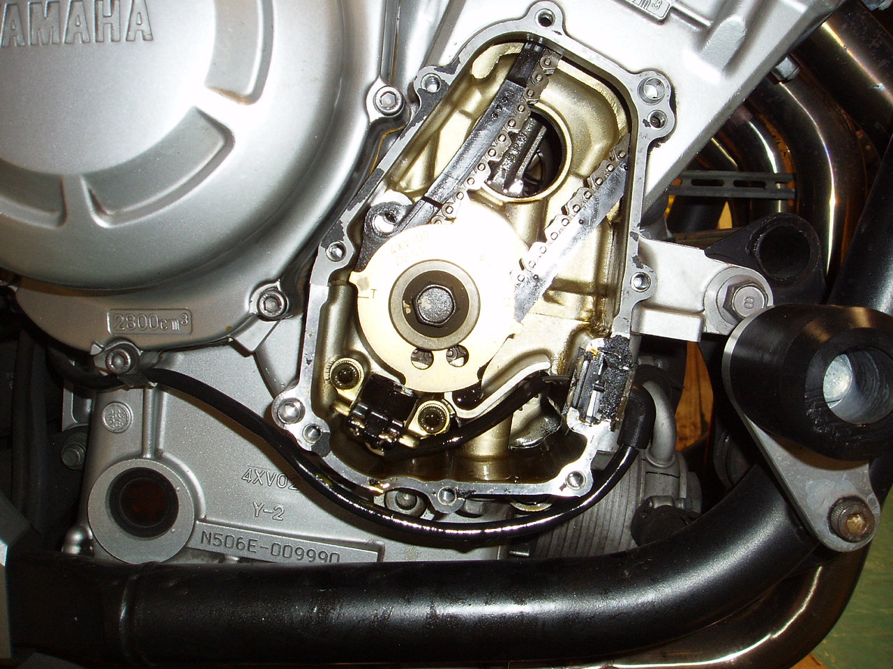
Next, in order to rotate the engine for valve clearance measurement, I removed the signal generator cover (5mm hex). Some oil seeps out of the engine when the cover is removed, so I put a drain pan underneath it. There are two long bolts, one at the top and the other at the bottom of the cover. Also a wire clip and a metal locating dowel that keeps the plastic cam chain guide in place. The locating dowel goes through a hole in the chain guide which aligns with a hole in the engine. The procedure calls for removing the cam chain guide which I didn't do. It's possible I should have as it was difficult to get the chain guide lined up to put the locating dowel back in. From the last photo you can see the cam chain guide hole is out of alignment with the guide hole in the engine.

Here are some views of the bike with the removal steps completed:


Front view: radiator, AIS, valve cover removed
Corrosion from two Salt Flats trips


Cam position for cyl 1 intake and exhaust valve check
Cylinder 1 at TDC on compression stroke


Signal generator in position for clearance check on cylinder 1
Note position of "T" mark

Having completed disassembly about 8 hours into it, I called it a day.

Sunday, June 6, 2010

Weekly Checks

I have a brief weekly routine to make sure the bike is in safe enough condition for another few days of weaving through traffic. This used to be my pre-flight check, and on an older bike it probably should be. But I found after months of daily checking, nothing much changed from day to day.
  • Check the oil level, add if appropriate (tip bike or put on centerstand)


  • Check tire pressure, inflate as needed - I put the Bandit at 36 front/39 rear. A sudden drop in pressure means a puncture.

  • Clean fork sliders with mild soapy water, rinse and dry - prolongs life of fork seals

Monday, May 31, 2010

Tank Removal

And now for a break from chain maintenance... occasionally other maintenance is necessary as well. On the Bandit it's necessary to remove the tank for many tune-up services including valve adjustment and carburetor sychronization.

Time

15 minutes

Materials
  • 2x4 or wood block
  • pliars
  • needlenose pliars
  • small phillps screwdriver
  • 10mm socket
  • rag
  • milk crate


Note, it's easiest to do this when there isn't much gas in the tank.

Steps
  • Remove the seat
  • Remove the fuel valve handle with a phillips screwdriver


  • Remove the two bolts securing the tank with a 10mm socket


  • Remove the rubber mounts underneath the two rear tabs on the tank


  • Pull the tank about 1" toward the back of the motorcycle, then lift the front and rest the front tab on top of the rubber mount at the front of the frame. When reinstalling the tank, note that this tab slides underneath the rubber mount.


  • put the 2x4 under the two tabs at the rear of the tank.


  • Disconnect the fuel sensor on the right side of the bike by pressing in on the lower end.


  • Disconnect the overflow hose behind the fuel sensor

  • On the left side of the bike, use the regular pliars to move the hose clamp down the braided hose a few inches, then disconnect the braided hose.


  • At this point the tank can be raised a bit more. Cover the engine with a rag to catch any gas that leaks after the next step.


  • From the right side of the bike, remove the vacuum hose from the fuel valve. Then use the needlenose pliars to loosen the hose clamp and disconnect the fuel hose. Fuel may drip from the fuel hose and/or fuel valve.


  • Tank may now be removed. Store it on a milk crate to avoid putting any pressure on the fuel valve. The seal is prone to leaking.


  • To reinstall the tank, reverse steps above. The two bolts securing the tank do not need to be very tight at all--finger tight plus half-turn at most.