Pages

Sunday, December 13, 2015

Eskort's FZ1 R/R Connector Fix, Day 3

Sunday December 13, 2015

Next step is the wiring harness side of the connector. This is the nerve-wracking part. It's one thing to wreck a $100 regulator/rectifier, another thing to wreck a wiring harness. Extreme caution was warranted.

The first step was to remove the burned connector. I labeled the white wires even though that's not supposed to be necessary. Was then unable to slide the metal connectors out of the plastic piece so I had to cut it off, leaving slightly less wire to work with. Then stripped the ends off the 5 wires.


Next, slide on the metal connectors, crimp and solder into place. As with the regulator side, the red and black wires were too thick to fit entirely into the connector. If I were to do this again I'd get the next size larger connector (30 amp) for these connections.

After jamming as much wire as I could into the connectors I crimped and soldered them on, filing off the extra solder as before. The soldering requires extreme precision to avoid melting any other nearby hoses, wires, or electrical connections. A lot of holding my breath.

With the plastic housings slid over the metal connectors I was able to start joining the 2 sides of the connection.


Per recommendation in Eskador's procedure I zip-tied the connectors together. I expected them to snap into place but they just sort of slid and stayed in place by friction, which seemed kind of haphazard. They did not want to stay joined by themselves which might seem to indicate a different connector.  So, zip ties.


Final connector bundle, all zip ties in place
The final test was to put the battery back in the bike, start it up, and check the battery voltage with the high beams on. Anything above 13.5 or so I'd probably call a success.


So, this is pretty good. Remains to be seen how long those connectors and my crappy soldering will hold up. So for the next few weeks I'll be checking the battery voltage as above every weekend.

Sunday, December 6, 2015

Eskort's FZ1 R/R Connector Fix, Day 2

December 6, 2015

Today in about 4 hours I was able to get the aftermarket connectors crimped and soldered onto the new regulator/rectifier. This was the easy part, if I messed up I'd only kill the new regulator/rectifier and not have to replace the bike's wiring harness.

The first step was labeling the white wires. Hypothetically they can go in any order but I'm paranoid.


Step 2, removing the OEM connector.


Next step is to slide on the new connectors, then crimp and solder them into position. This went fine, except the red and black wires seem to be a thicker gauge than the white wires. So there was more wire than what would slide into the PowerPole connector. I did what I could, which was to jam as much wire into the connector as possible, then solder the excess wire to the outside of the connector and file down the excess. Not ideal to be sure.


After the connectors are soldered on the plastic housing slides over until it clicks into place. The technique is to hold the bottom end of the connector with needle-nose pliers and slide the housing over the connector until it clicks.


After all the connectors are on, the new regulator is mounted on the bike and the cable is routed into position.


White marks on the connectors are to note white wires. That was another 4 hours' work, and the end of the 2nd day of the project.

Saturday, December 5, 2015

Implementing Eskort's R/R Connector Fix on the Yamaha FZ1

December 5, 2015

Having received the crimper, regulator/rectifier, and connectors it was time to implement Eskort's connector fix.


The first step was to remove the old regulator/rectifier, which is under the front fairing left side panel. The plug into the wiring harness is underneath the tank, so unbolting the front tank bolt and propping up the tank is necessary.


R/R under fairing left side panel

I did a bit of experimenting with the old regulator/rectifier to see if I could get the plug off without cutting the wires, and it turns out it is possible. By going into the front of the connector with a mini-screwdriver and pressing a metal tab, the connector will slide out of the white plug. This gives a little bit extra wire to play with, in case something went wrong with the aftermarket connector installation.


Out of time, to be continued...


Friday, November 13, 2015

FZ1 Charging System Woes

November 13, 2015

The FZ1 has been having ongoing charging system issues. Went out the first time on the way to work late at night in August. First the speedo & tach went dead so I knew something was wrong. Then a few miles later the dash went out, then the lights, finally coasted to work with the engine barely running. Still had to work all night of course, then figure out how to get home.

So I bought a new OEM battery from Mach1 Motorsports, brought it to work the next day, swapped it out in the parking lot, and was able to make it home on battery power only.

Over the weekend I was able to do some charging system troubleshooting using my trusty Harbor Freight multi-meter and an electrical system troubleshooting flowchart from electrosport.com. So I found the alternator was putting our 18VAC, the battery of course was new, and I was never sure of the readings I was getting from the regulator/rectifier. So I replaced it ($135 OEM at motosport.com).

So the bike ran fine for a few months, then on the way home from work Friday the 13th the dash started looking a bit dim. I thought maybe it was my night vision. Then closer to home the needles started bouncing--sure sign of trouble. Finally as I pulled into the driveway I hit the high beams and the dash went out, so I knew the charging system was dead again.

Not having another 2 hours to spend with my multi-meter and the flowchart, I called Mach1 and tried to make an appointment for charging system diagnosis. They asked the year of the bike, so I told them '03, and they said they didn't really like working on stuff that old. I was like, "really?" They asked some questions about the condition of the bike, whether it was a basket case, etc. and I finally said, let me just bring it by, and if it looks like something you don't want to deal with I'll take it home. Their first available appointment was 2 weeks out so I scheduled it, feeling like I didn't have much of a choice.

There is a lot of editorial comment I could make here about the state of motorcycle repair shops, how they're only interested in selling new bikes and turning around the easiest jobs to make the most profit possible. I wouldn't think any reputable auto mechanic would turn away a 12-year-old car with 79k miles. But that is another topic.

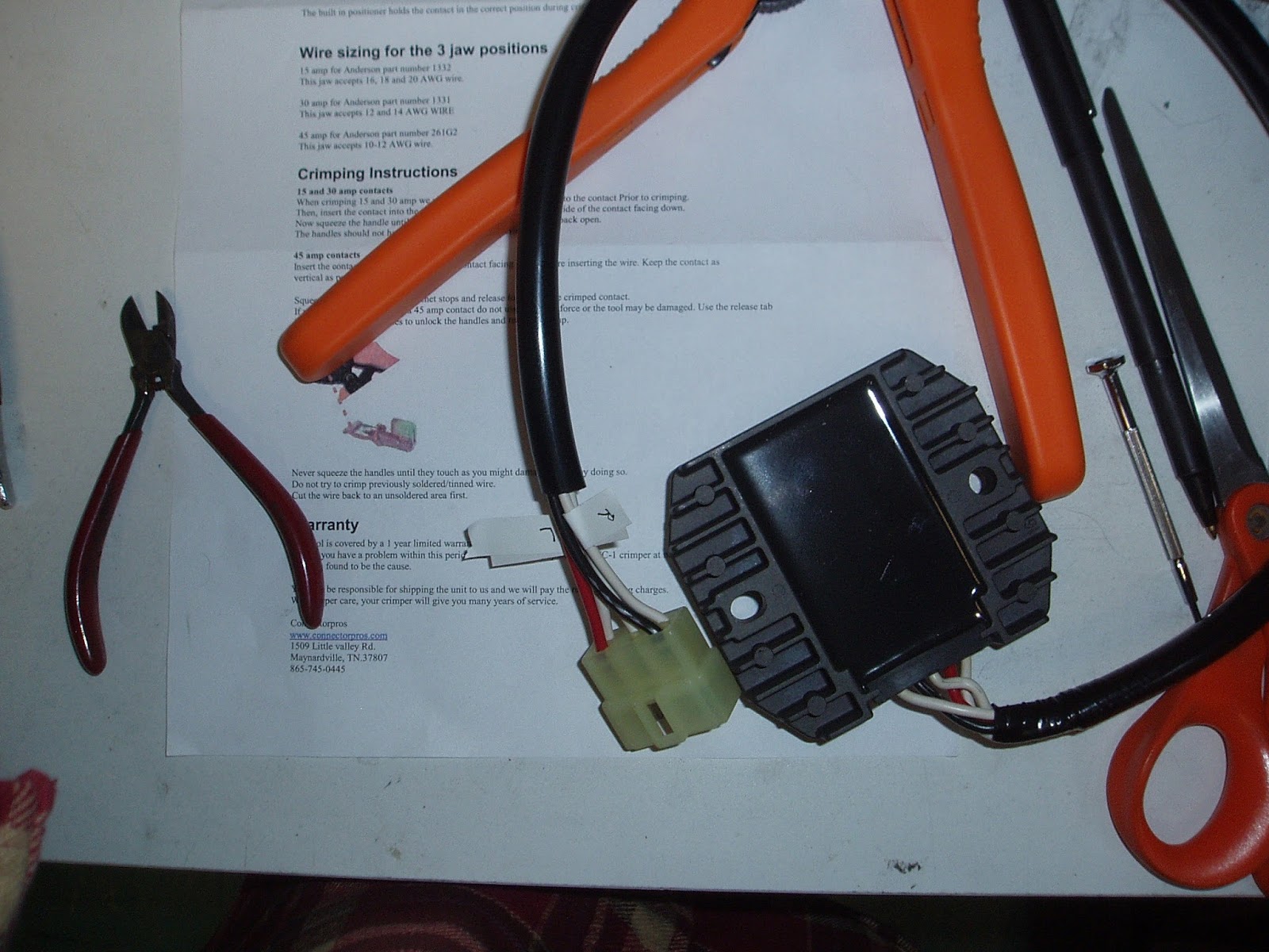
Now the bike had been sitting idle in the garage all this time, and I started feeling bad, so I decided the least I could do would be to look for bad wires or loose connections. So I propped up the tank and disconnected the regulator, and found my bike had succumbed to the infamous white connector problem:


The white connector is a known source of issues in 1st gen FZ1s. It's bitten enough FZ1 owners that there is a 
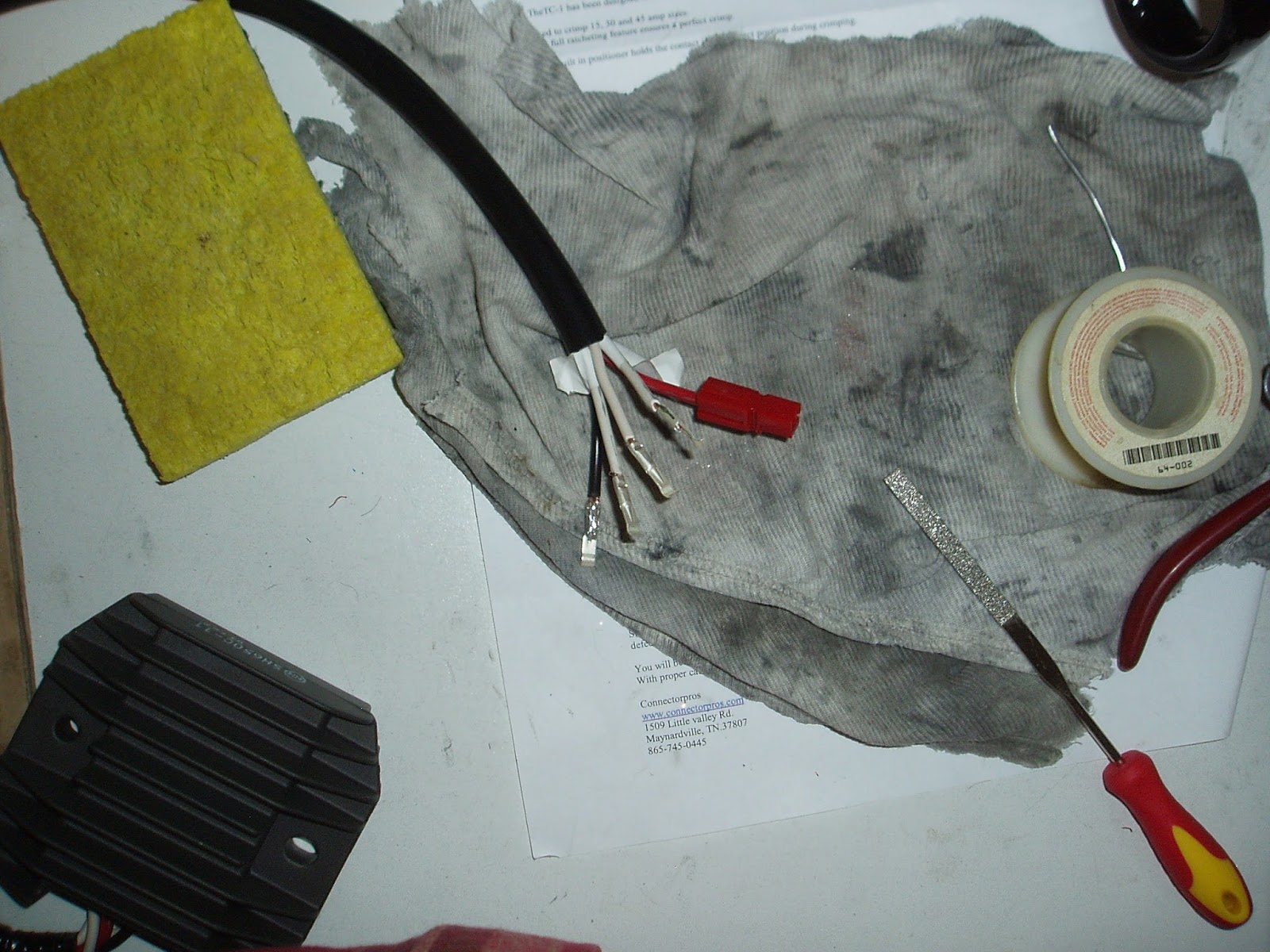
connector fix on the FZ1 owner's list, but unfortunately the author, Eskort, didn't list what type of connectors he used as replacements. So I sent him a forum PM, heard nothing for a few days, then emailed him via the forum. He responded a day later with a link to a pack of Anderson Powerpole 15 amp connectors ($7.50 + $4.49 shipping). So I canceled my shop appointment. They were polite about it.

I also bought a crimper ($38 on amazon), which I wasn't sure if I'd need but seemed like a good thing to have. Finally, another OEM regulator/rectifier from MotoSport ($135), noting also that Rick's Motorsports sells an aftermarket regulator/rectifier for slightly cheaper (around $90). Maybe next time.

Hopefully for slightly under $200 I'll have the charging system fixed once and for all. Will write up the mechanical work once I get the parts (early December).


Sunday, November 8, 2015

FZ1 Seat Repair

November 8, 2015

Unfortunately missed the opportunity to write up the Bandit's front brake and clutch line replacement, and master cylinder rebuilds. I'll be doing the rear brake line and master cylinder soon so I'll be sure to write that up.

The Yamaha developed a rip in the seat a year or more ago. It was near the front at the seam, and it continually got worse as time went on. Well, there's nothing to make a bike look more shabby than a ripped seat so I decided to get it fixed, or replace the seat. Unfortunately I don't have a photo of the rip. I didn't like to look at it.

Not knowing where to go I googled up motorcycle seat repair and found Motorcycle Scooter Upholstery on yelp. It's not a storefront, just a guy who does seat work out of his garage. So I gave a call to the number on the yelp page, and a guy in a heavy accent told me to drop by with the seat at noon on Saturday.

The address he gave me was way out in the outer Sunset in SF, almost a 90-minute ride from where I live. So I strapped the seat to the Bandit and rode over the Golden Gate Bridge ($6.25) to the City.

To make a long story short, Tony worked on it while I waited to save me a 2nd trip. It was not cheap ($85, cash only), and took 2 hours. He replaced everything forward of the front seam, a small piece of leather sewn in. The rest of the seat is still the original vinyl material. But it looks completely OEM, you'd have to know it was repaired. So I'm happy with the work, and I guess for 2 hours and materials $85 is reasonable. Some photos of the repair. The new leather is at the front of the seat, the rest is original.


Saturday, January 17, 2015

FZ1 Pazzo Racing Levers

January 17, 2015

As a final winter upgrade, inspired by a bent clutch lever I replaced the FZ1's OEM levers with Pazzo Racing levers. I'm usually not into "bling" (decorative upgrades), but these are really nice levers that go well with the OEM black bars.  They do have an easy adjustment switch feature that is nicer than the stock levers.

Pazzo levers
The FZ1 levers are PN# F-14 brake and Y-688 clutch.  Note that they are quite a bit shorter than OEM levers.

OEM clutch lever


Installation
 
Installation takes 10 - 15 minutes.  Simply unbolt the OEM lever with a 10mm socket.  The brake lever also requires a flat screwdriver to unscrew it from the top.  Clean bolts, regrease them, bolt in new levers.  Threading the clutch cable into the new lever is straightforward.

Pazzo brake lever
Pazzo clutch lever

Brake lever detail
Clutch lever detail

Riding Impression

As the levers are shorter the action is more abrupt than the OEM levers and takes a bit of getting used to.  The first thing I did was back down the driveway and stall the bike.  Also it's not possible to get more than 3 fingers on the levers.  This has not been a problem so far.  After a few rides they feel natural but there is a brief period where they're a bit clumsy.

Edit 2015-11-21: Unfortunately after about a year with the short levers I succumbed to wrist and shoulder pain in my clutch arm. So I had to replace the Pazzo levers with OEM. If I can find regular length Pazzo levers I'll get those, but there are more important mechanical issues at the momement.

Sunday, January 11, 2015

FZ1 Holeshot Stage 1 kit, part IV: Timing Advancer

January 11, 2015

A timing advancer is included in the Holeshot FZ1 Stage 1 kit.  The idea is to replace the stock timing disk under the right side engine cover with a disk that causes the spark to fire slightly sooner. According to the Holeshot site this improves gas mileage, throttle response, and allows the use of regular 87 octane gas.

FZ1 Timing Advancer kit
Interestingly the Holeshot site advises not to run the timing advancer without first installing the Stage 1 kit while it claims the slip-on can be run with the stock carburetor settings.  While I trust Dale's judgment I wouldn't install any performance upgrades without first doing the carburetor tuning (Stage 1 or Stage 2 kit or equivalent).  To do otherwise is asking for trouble in my opinion.

There were a few reasons why I delayed installing the timing advancer, the most important being none of the installation methods were very appealing.

I've installed Holeshot timing advancers on 2 Bandits and the install is trivial.  Unbolt the right side engine cover, remove a hex bolt, swap timing disks, reinstall the bolt, and put the engine cover back on.  30 minutes at most if there are engine guards in the way.

Unfortunately the bolt securing the timing disk on the FZ1 also turns the motor.  So there is no way to remove it with a regular socket wrench without finding some way to stop the engine from turning with the bolt as you turn it.  Otherwise the engine turns and the bolt never gets loose.

The Holeshot kit instructions outline 3 ways to do this, none of which I liked.
  1. Dale's recommendation:  spin the bolt out and reinstall with an air impact wrench, using red threadlock on the bolt.  I don't like using air tools unless there are no other alternatives because of the high amount of force delivered to bolt heads and threads.  And I don't like threadlock.
  2. Put the bike in 6th gear, step on the rear brake to hold the rear wheel in place (thus holding the motor), and loosen the bolt with a socket wrench.  Internet variation, put a 2-by-4 through the rear wheel rim underneath the swingarm to block the wheel from moving when the motor tries to turn.  Not recommended by Dale due to stress put on internal engine/transmission components, and I tended to agree with that.
  3. The manual's preferred method: purchase a Yamaha magneto rotor holder, Yamaha PN# 90890-01235 ($129 at the local shop), remove the right side cover and hold the alternator rotor with the rotor holder to stop the engine from turning, while turning the bolt loose on the left side.  Requires replacing the right side cover gasket (Yamaha PN# 4XV-15451-00-00, $7.00).  Not recommended by Dale due to time and expense involved.
Ultimately I decided to go with option #3, being safest.  $150 and 3 days later I was the proud owner of a Yamaha YU-01235 magneto rotor holder and alternator side cover gasket.

With the rotor holder the install is not difficult and can be done by one person.  First remove left and right side covers, keeping the bolts in order as they are different lengths.  Some oil will drain from each side.

Right side cover bolts in order
Left side cover and bolts in order
Remove old right side cover gasket.  This was the hardest part, about an hour of painstaking scraping, attempting not to gouge gasket mating surfaces on the engine and cover.  Place rotor holder tabs into appropriately-sized holes in alternator rotor.  I put a rag on the handle and braced it against the frame slider.

Rotor holder
With the rotor holder in place it was easy to remove the timing bolt.

OEM timing disk and bolt
Holeshot timing advancer and OEM timing disk
The next step was to simply swap the timing disks and bolt in the Holeshot timing advancer (writing side out).  Then bolt the covers back on and check the oil level.

Holeshot timing advancer installed
Initial Ride Test

The timing advancer does make a difference.  The bike is quicker taking off from a stop and I haven't had any trouble with 87 octane gas (I only use Chevron though).  As far as gas mileage it seems like I'm not doing quite as well as before but the difference is not that much.  Part of the issue is I ride the bike differently now (more throttle all the time) since it performs and sounds better.  Roll-ons destroy mileage!