Pages

Sunday, December 13, 2015

Eskort's FZ1 R/R Connector Fix, Day 3

Sunday December 13, 2015

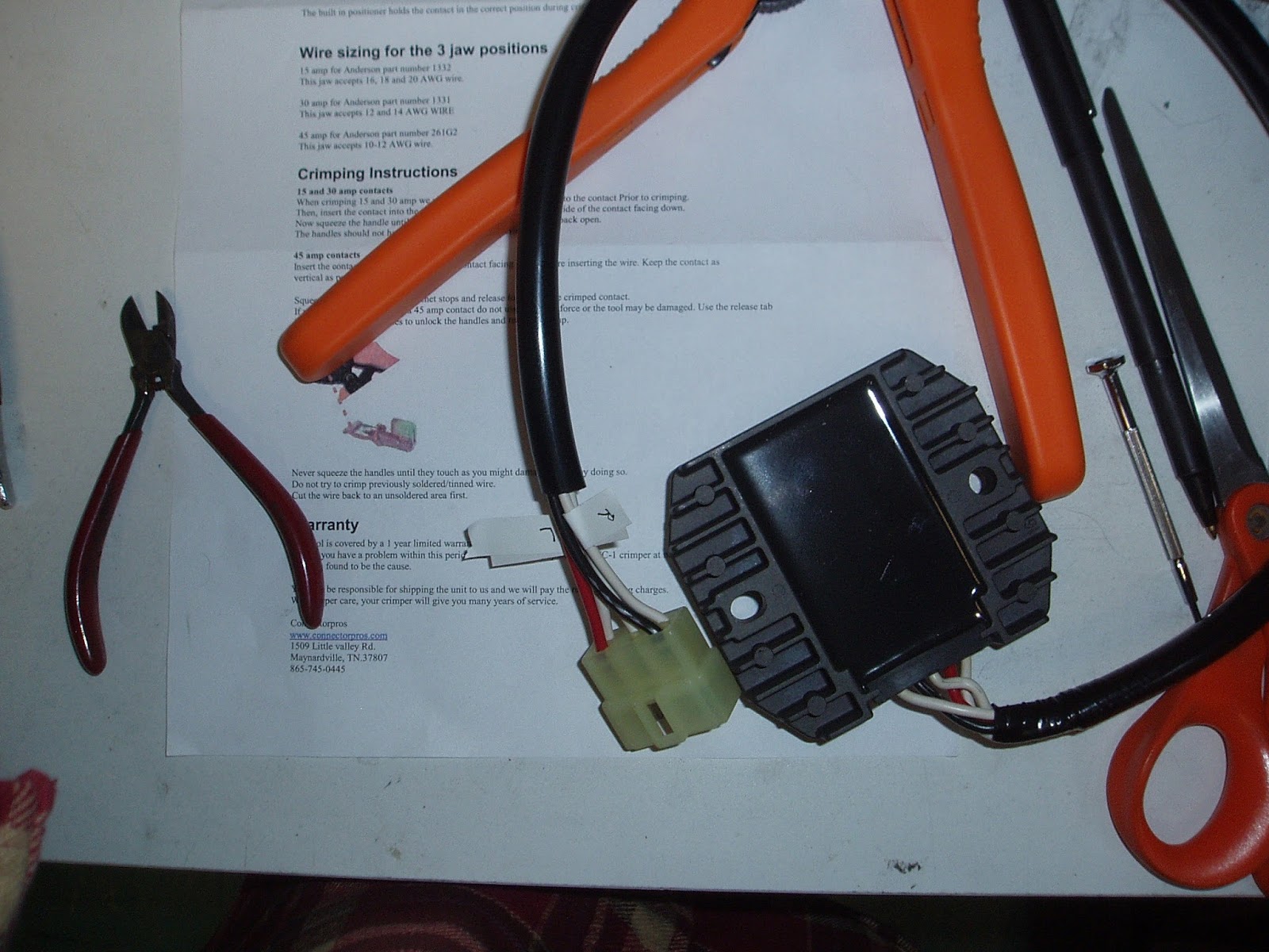
Next step is the wiring harness side of the connector. This is the nerve-wracking part. It's one thing to wreck a $100 regulator/rectifier, another thing to wreck a wiring harness. Extreme caution was warranted.

The first step was to remove the burned connector. I labeled the white wires even though that's not supposed to be necessary. Was then unable to slide the metal connectors out of the plastic piece so I had to cut it off, leaving slightly less wire to work with. Then stripped the ends off the 5 wires.


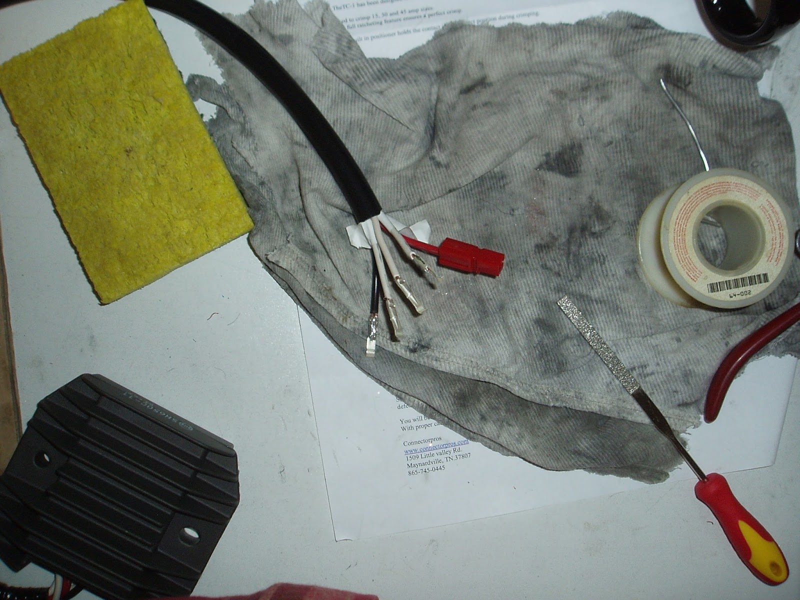
Next, slide on the metal connectors, crimp and solder into place. As with the regulator side, the red and black wires were too thick to fit entirely into the connector. If I were to do this again I'd get the next size larger connector (30 amp) for these connections.

After jamming as much wire as I could into the connectors I crimped and soldered them on, filing off the extra solder as before. The soldering requires extreme precision to avoid melting any other nearby hoses, wires, or electrical connections. A lot of holding my breath.

With the plastic housings slid over the metal connectors I was able to start joining the 2 sides of the connection.


Per recommendation in Eskador's procedure I zip-tied the connectors together. I expected them to snap into place but they just sort of slid and stayed in place by friction, which seemed kind of haphazard. They did not want to stay joined by themselves which might seem to indicate a different connector.  So, zip ties.


Final connector bundle, all zip ties in place
The final test was to put the battery back in the bike, start it up, and check the battery voltage with the high beams on. Anything above 13.5 or so I'd probably call a success.


So, this is pretty good. Remains to be seen how long those connectors and my crappy soldering will hold up. So for the next few weeks I'll be checking the battery voltage as above every weekend.

Sunday, December 6, 2015

Eskort's FZ1 R/R Connector Fix, Day 2

December 6, 2015

Today in about 4 hours I was able to get the aftermarket connectors crimped and soldered onto the new regulator/rectifier. This was the easy part, if I messed up I'd only kill the new regulator/rectifier and not have to replace the bike's wiring harness.

The first step was labeling the white wires. Hypothetically they can go in any order but I'm paranoid.


Step 2, removing the OEM connector.


Next step is to slide on the new connectors, then crimp and solder them into position. This went fine, except the red and black wires seem to be a thicker gauge than the white wires. So there was more wire than what would slide into the PowerPole connector. I did what I could, which was to jam as much wire into the connector as possible, then solder the excess wire to the outside of the connector and file down the excess. Not ideal to be sure.


After the connectors are soldered on the plastic housing slides over until it clicks into place. The technique is to hold the bottom end of the connector with needle-nose pliers and slide the housing over the connector until it clicks.


After all the connectors are on, the new regulator is mounted on the bike and the cable is routed into position.


White marks on the connectors are to note white wires. That was another 4 hours' work, and the end of the 2nd day of the project.

Saturday, December 5, 2015

Implementing Eskort's R/R Connector Fix on the Yamaha FZ1

December 5, 2015

Having received the crimper, regulator/rectifier, and connectors it was time to implement Eskort's connector fix.


The first step was to remove the old regulator/rectifier, which is under the front fairing left side panel. The plug into the wiring harness is underneath the tank, so unbolting the front tank bolt and propping up the tank is necessary.


R/R under fairing left side panel

I did a bit of experimenting with the old regulator/rectifier to see if I could get the plug off without cutting the wires, and it turns out it is possible. By going into the front of the connector with a mini-screwdriver and pressing a metal tab, the connector will slide out of the white plug. This gives a little bit extra wire to play with, in case something went wrong with the aftermarket connector installation.


Out of time, to be continued...